Selecting Pneumatic Valves
Pneumatic valves are one of the most popular varieties of actuated valves. The devices are clean, efficient, and have an excellent force-to-size ratio. They are used in various fluid control applications across numerous industries. Pneumatic valves have several benefits in fluid control. However, there are of multiple types with unique characteristics and advantages, so you need to select the right one for your application. Correctly choosing the suitable pneumatic valve for an application requires a good understanding of what the devices are.
Valves are fluid control devices that control and modulate the flow of media in a piping system. They employ various types of blocking mechanisms that physically obstruct or allow the flow of media. Valves may be manually controlled or actuated. Also known as automated valves, actuated valves are assembled with actuators that operate without human intervention. Depending on how it generates the required force, an actuator can be electrical, pneumatic, or hydraulic. Valves coupled with actuators are commonly viewed as a single unit and named accordingly. For example, a butterfly valve that is coupled with a pneumatic actuator is referred to as a pneumatic butterfly valve.
Pneumatic valves are of various builds and configurations. Therefore, certain factors must be carefully considered in order to select the right one for your application. The following are some of these factors.
Media
The first consideration in selecting the best pneumatic valve for your application is to consider the type of fluid that will flow through it. The fluid could be liquid, gaseous, or sludge, among others. Also, it is vital to consider the flow pressure. The media could be compressed air, water, or have a flow with negative pressure. This consideration has to be made to ensure that the compatible valve is selected for the application.
Actuation type
Pneumatic actuators may be double-acting or single-acting. Commonly referred to as spring return actuators, single-acting actuators have a compressed spring located on one side of the piston. The spring holds the valve in its original position. To operate the valve, compressed air introduced on the opposite side of the piston surmounts the spring’s force. Once the air supply is shut off, the spring returns the valve to its original position.
In double-acting actuators, however, pressurized air at different pressures is supplied to the piston from both sides. The pressure difference between the two sides keeps the valve in the required position – open, closed, or partially open and closed.
Single-acting pneumatic valves are suitable for open and close control, but for a more controlled modulation, their double-acting counterparts are more common. However, when accompanied by a positioner, single-acting spring return actuators on v-ball control valves can implement modulating control. Other considerations when selecting between a single- or double-acting actuator include weight, size, and cost.
Valve materials
Valve materials are of high importance in selecting the right valve for your application. The right materials reduce the risk of failure during operation. For example, using uncoated valve materials in a chemically aggressive environment leads to rust and failure of parts. Epoxy-coated actuators are resistant to most chemicals, but they are not suitable for conditions in which they are fully submerged by the media. For this sort of application, stainless steel is a better option. Brass valves are perfectly adequate if the media is water. Another option is to use high-temp seal kits that enable you to tailor a certain valve’s suitability for a particular application. However, keep in mind that choosing the correct valve material is still the most important part of the process.
Flow capacity
Essentially, a valve, once it’s opened, has to deliver enough flow to fill up a specific volume downstream within a given period. An undersized valve delivers less flow, increasing the time needed to fill up downstream. An oversized valve is simply an extra cost in the system. Therefore, it is essential to determine the maximum flow volume expected during operation and select a suitable valve with adequate capacity. Knowing the right valve capacity is easy, as many manufacturers provide the flow capacity of their valves and reference materials.
Operating environment
Pneumatic valves are affected by their operating environment. Environmental factors include ambient temperature, exposure to chemicals, vibrations, and so forth. Valve components, especially the pneumatic cylinder, have their fundamental operating temperature and must be considered before introduction into any working environment. A dry, nonaggressive environment does not require specially coated valves. A humid environment does require coating on the external components of the valve. Another operating environment that affects the choice of valve is the medical or food industry. Such environments may require a valve of certain certification or “clean” design features.
Valve type
Different pneumatic valves are best suited for different applications and operating conditions. For example, a butterfly valve is a poor choice for high-pressure applications and has a higher head loss. On the other hand, ball valves are more suitable for high-pressure applications due to the nature of the ball; they also have lower head loss. Actuating a ball valve in a high-pressure flow system is easier compared to actuating a butterfly valve. However, butterfly valves are popular in huge diameter lines for isolation. Always select the best valve build for your application.
Installation area
Pneumatic valves are air-actuated valves. The air usually comes from an air compressor strategically positioned in the work environment. It is therefore vital to ensure that the application environment is adequately inspected for space that should be adequate to accommodate the right-size compressor. The compressor determines the pressure at which the actuating mechanism receives air. The available air for actuation thus influences the size of the actuator required to deliver the required force to actuate a valve.
Installation orientation
For most valves, the direction of flow is horizontal, and since the actuator is installed on top of the valve, its installation orientation will be vertical, that is, upright. As much as possible, avoid horizontal actuator installation. This is because the pressure is exerted on one side of the packing, which will experience wear, leading to leaks in the valve.
Pneumatic valves are fast, reliable, and efficient devices for fluid control. Selecting the right type for an application is vital to the application’s success. Careful consideration of the factors discussed above will ensure that you select the best pneumatic valve for your application.
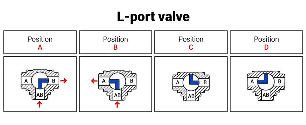
IMAGE 1: L-port valve: one inlet

IMAGE 2: L-port valve: two inlets
To illustrate how L-ports operate, consider a three-way ball valve with port AB as its inlet. Assume the fluid flows from the inlet port and travels in the right direction towards outlet port B, as illustrated below (Position A). The three-way valve contains a lever or actuator that moves 90 degrees to alternate the direction of fluid flow. When the lever travels 90 degrees clockwise, the ball blocks fluid flow through port B and redirects it towards the left–port A, which becomes the new outlet.
Another quarter turn moves the valves 180 degrees from their original position. At this point, the ball blocks the fluid flow through both outlet ports, and there is a total shutoff to fluid flow. Certain L-port valves can turn 360 degrees and have
two shutoff positions. L-ports can be installed in horizontal and vertical configurations. Port AB remains in an open position if the L-port valve is installed in a vertical pipe configuration.
T-Port valves
T-port valves are vital for converging (mixing) fluids from two sources and delivering them through a common outlet. The valves are essential for splitting fluids from one source in two directions. Therefore, these valves can have two inlets and a single outlet port or one inlet and two outlets. When using T-ports for fluid control in industrial processes, all the ports are in an open position at once. It implies that the valves can achieve the uninterrupted straight-through flow of service fluids. Like the L-port, T-port valves can fit in vertically and horizontally configured pipelines.
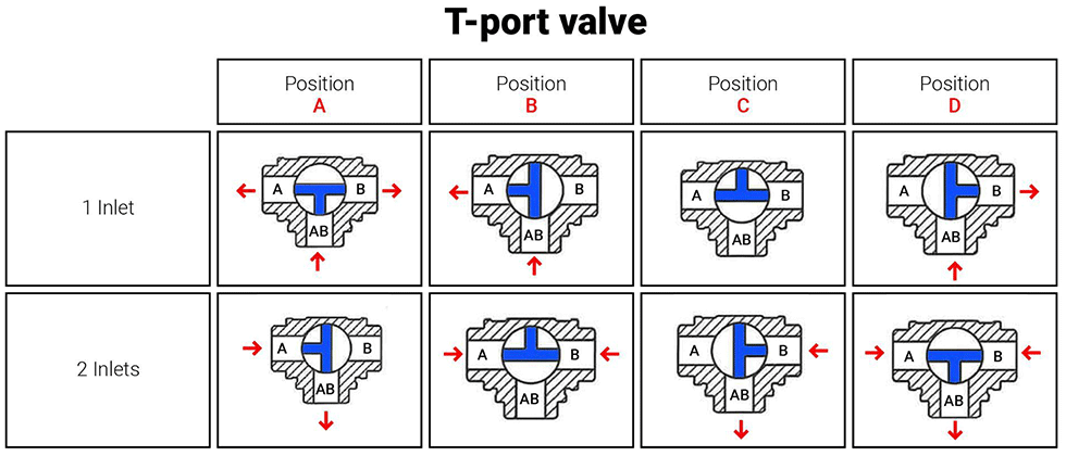
IMAGE 3: T-port valve (diverting fluid service)
Actuating T-port valves 90 degrees causes them to depict similar performance characteristics as L-port, three-way valves. Fluid will flow from the common inlet and travel through one outlet port alone. Actuating the valve 180 degrees is inconsequential to fluid flow. One shortcoming of T-port valves is their lack of bubble-tight shutoff. These valves are unsuitable for pipelines demanding strict control of leakages and fugitive emissions. T-port valves are fitted with lock handles that control the quarter turn transitions of the flow control mechanisms. This feature facilitates better volumetric control when mixing or diverting service fluids.
Practical Applications of Three-Way Valves
T-port valves are mostly used for mixing services in industrial applications. The valves are connected to pipelines transporting different fluid compositions. As the fluids from the diverse sources merge at the valve, they mix in controlled proportions before moving to subsequent pipe sections or processes. T-port valves usually provide constant flow control, assisting engineers in mixing and sampling fluids at different pipe sections.
Diverting fluid flow is possible using L-port and T-port valves. L-port valves provide a fluid diversion to one direction at a particular time. However, T-port valves can divert fluids to two destinations at once. T-port valves can also allow for straight-through flow (from inlet port A to outlet port B), which could be diverted 90 degrees to the second outlet port AB. It is a common set up in T-port valves used in diverting applications, as this cannot be accomplished with an L-port arrangement. L-port valves can divert fluid between two storage tanks. Once one tank fills up, the valve (if automated) changes its position and directs incoming fluid into the empty tank. Depending on the configuration, T-port valves can also act like L-port valves to divert fluid flow between storage tanks.
Three-way valves can be manually operated or automated using electric, pneumatic or hydraulic actuators. The type of actuator used depends on the desired level of valve automation, level of responsiveness and the actuation forces required.
Pneumatic actuators are preferable for their cost-effectiveness and ability to sustain multiple valve cycles. Hydraulic actuators can provide better actuation torque but are more costly than pneumatic actuators. Some three-way valves are actuated using electrical actuators, which offer better precision but have lower duty cycles than pneumatic actuators. Three-way valves can provide flexible flow control in different applications. The multiple ports allow process engineers to customize industrial processes using fewer valves.